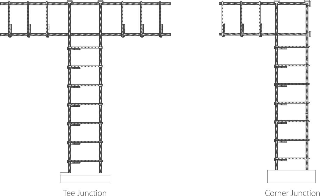
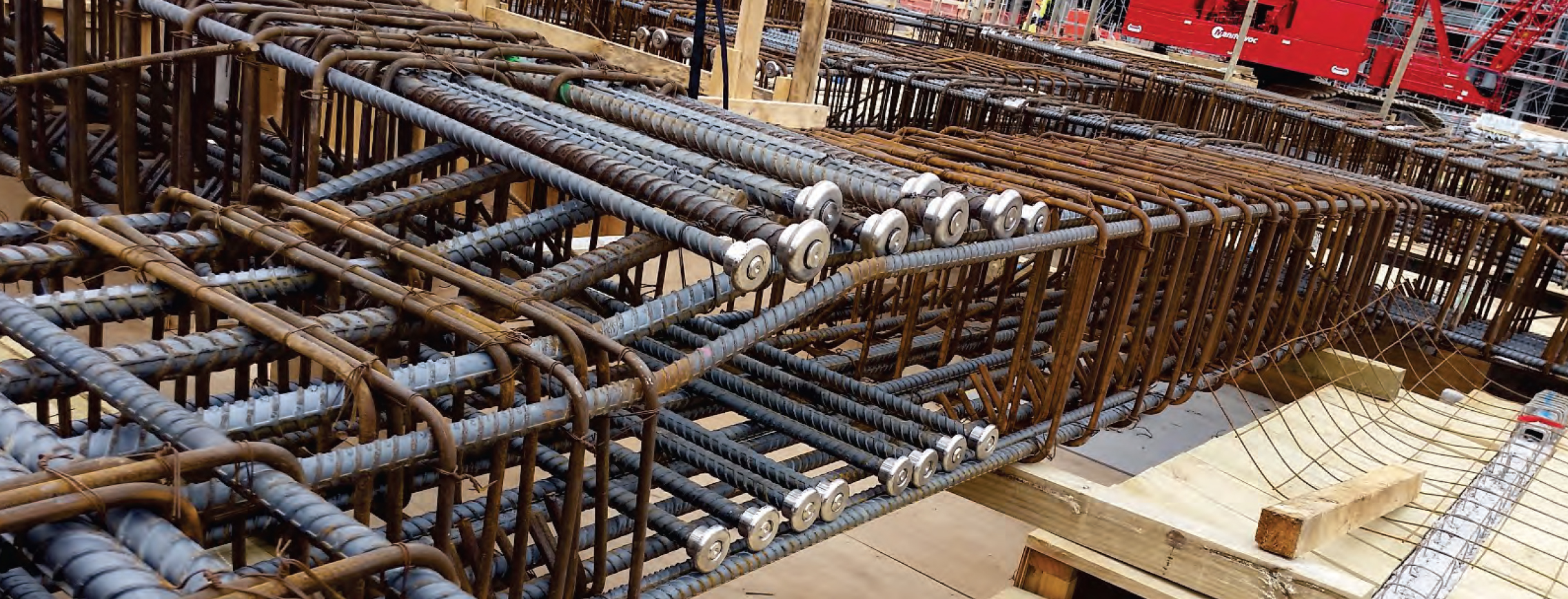
This technical guide is designed to provide guidance to the use of Cage BMS —Terminators when mechanically spliced to reinforcing bar. This guide covers the design of reduction in reinforcing development length due to the use of our Cage BMS Terminators and the manufacturing Quality Assurance processes undertaken.
1.1 SCOPE
In the process of proportioning reinforced concrete members there are many situations in which the amount of space available is not sufficient to fully develop or anchor straight reinforcing bars subjected to tension. The most commonly used technique to reduce the required development length of bars subjected to tension is to terminate the bars using a 90 Deg or 180 Deg hook. Although hooks are helpful in reducing development length their use sometimes brings about congestion and other detailing problems.
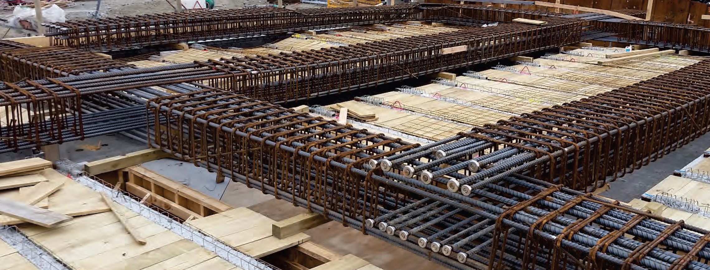
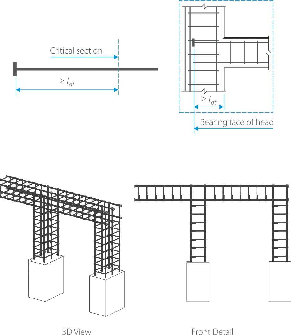
An alternative method to reduce the required development length of straight bars in tension is the use of”Heads”to anchor the end of the bar in the surrounding concrete through the introduction of bearing.
Bars with “Headed Ends” can be used to alleviate congestion and detailing problems otherwise associated with hooked ends and long development lengths. This is because a headed bar typically requires a shorter development length than a straight bar or hooked bar.
1.2 RELATED STANDARDS
| A. Anchorage: | AS3600, ACI-318, ACI-349, ACI-352 |
| B. Material: | 1 Reinforcing bar: AS/NZ 4721, BS 4449, ASTM A615, KS D 3504 |
| 2 BMS-Terminator: KS D 3752, ASTM A108 |
1.3 DEFINITION OF NOTATION
A. Reinforcing Bar
The material used in production of the reinforcing bar should met the steel requirements in accordance with AS/NZ 4721, BS 4449, ASTM A615 of KS D 3504.
B. BMS-Terminator
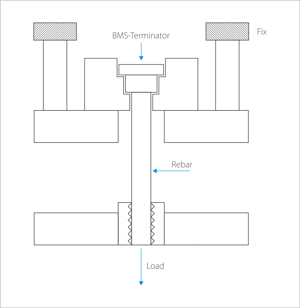
The combination of a reinforcing bar with a mechanically spliced headed end. The process is to mechanically splice the two together by a process of applying a thread to the reinforcing bar and screwing a threaded head onto the bar.
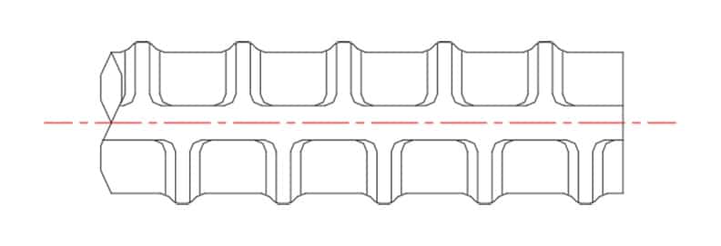
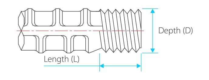
1.4 PROCESS OF THREADING REBAR
Cage BMS use a combination of cold forging and cold rolling the reinforcing bar to produce a high strength precisely formed thread.
The reinforcement bar is swaged (moulded) to produce a round bar profile of a set size. This swaging process aligns the grain flow of rib and the core diameter improving the localised tensile characteristics.
This round profile is then cold rolled to produce the desired thread. This cold rolling process results in increased thread yield strength, surface hardness, and improved surfaced finished, in turn producing improved fatigue and wear resistance of the thread.
C. BMS-Terminator Shape
The shape of the actual headed end to be spliced onto the reinforcement.
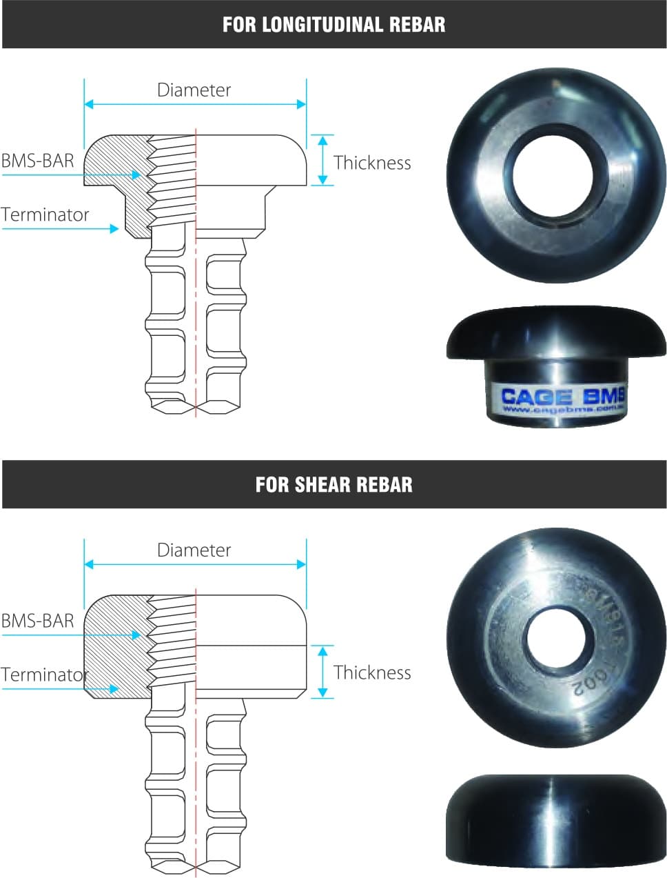
BMS-TERMINATOR
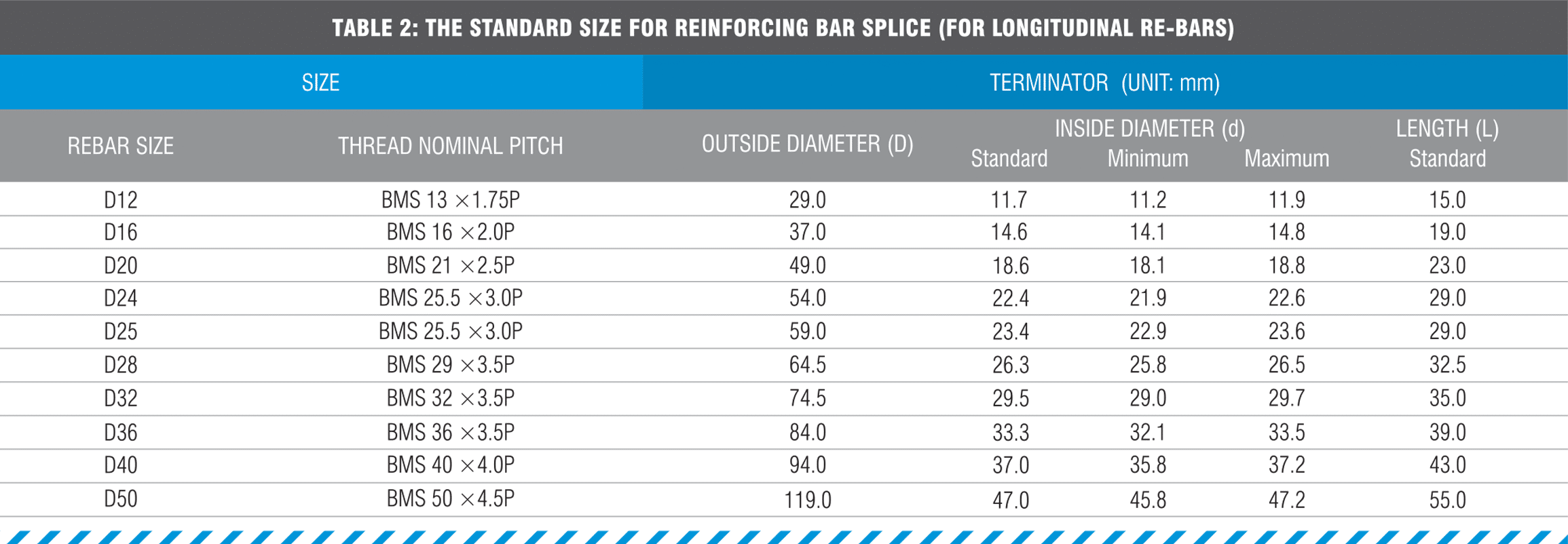
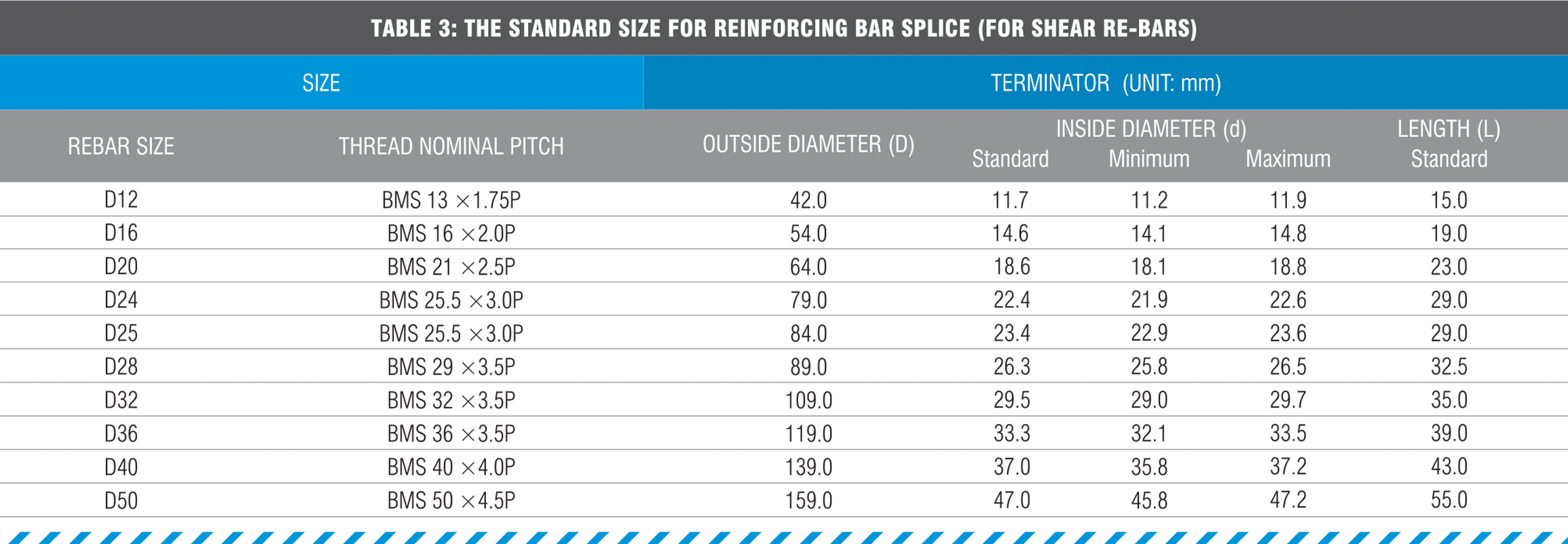
2.1 DESIGN FOR THE TERMINATOR
*The granting method of LOT No.: ex) BMS D40T-000
DEVELOPMENT LENGTH OF REBAR USING AS3600
When looking to utilise our BMS Terminators in Australia then design standard AS 3600 – Section 13 (Stress Development of Reinforcement and Tendons) provides guidance in calculating the development length.
3.1 BASIC DEVELOPMENT LENGTH
Idt = >0.058*fy*kidb
fy Rebar yield point
db Rebar diameter
ki = 1.3 (assumed)

Australian Standard AS3600 – Section 13.1.4 (requires 4x)
3.2 DEVELOPMENT LENGTH OF REBAR WITH BMS-TERMINATOR
Idt x 0.5 when A head/A bar= 4
A head Net bearing area of the terminator
Abar Cross-sectional area of bar
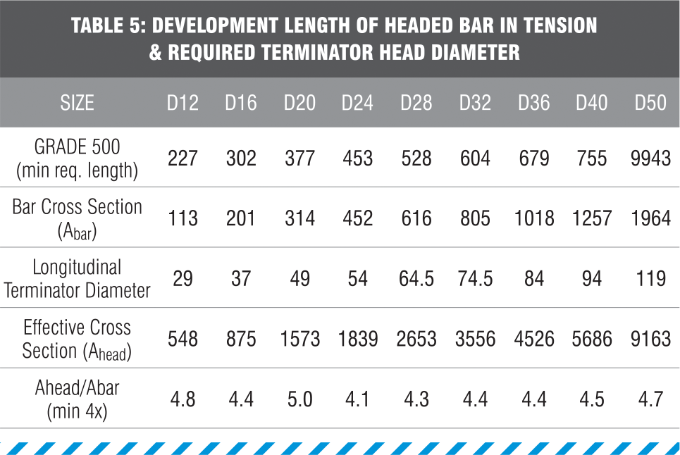
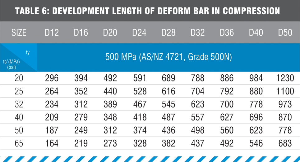
3.3 DEVELOPMENT LENGTH OF BMS-TERMINATOR Idt

fy Rebar yield point
lc‘ Concrete Compressive strength
db rebar diameter)
TERMINATOR INSTALLATION
4.2 MATTERS TO BE ATTENDED ON SPLICING CONSTRUCTION
A. Prior to the coupling installation, check the placement
of the original bars, coupling position, coupled area and parts, cleanness and inspect the installation tools for complete performance with designated instruments as specified in installation instruction.
B. As like the clause 4.1
- Assemble Terminator and threaded reinforcing bar
- Placement, band wire and fixed
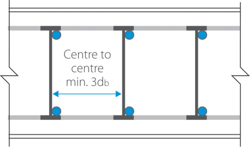
4.3 PLACE DIMENSION
QUALITY INSPECTION & CONTROL
5.1 MATERIAL INSPECTION
A. BMS-Terminator
- The material to be used in the Terminator shall be the chemical component specified in accordance with (Table 5).
- The noxious substance such as oil shall not be existed because the cleanliness of terminator relates to the attachment of concrete.

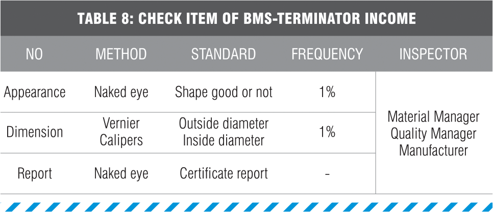
5.2 INCOME INSPECTION OF BMS-TERMINATOR ON-SITE
5.3 THE TIGHTENING INSPECTION ON THE SPLICE PART
1. Confirm the whole splicing part about the cleanliness on the thread part of reinforcing bar, Terminator to attain the splicing performance of the reinforcing bar in the splice part by eye before the splice construction.
Reference:
- If the rust occur on the thread of reinforcing bar extremely and it is hard for the thread to couple, use the thread after the removal of rust by using the Wire Brush(Wheel type). If it is hard for thread to couple due to the extreme occurrence of the rust on the Terminator, use by exchanging to another product.
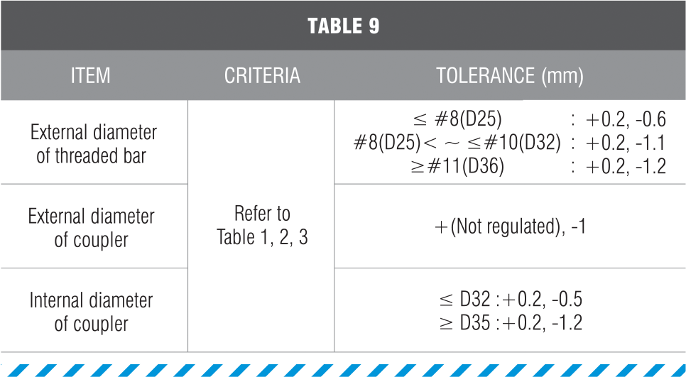
- Modify the part of fracture with triangular file when the thread part of reinforcing bar is damaged and the damaged area is determined according to the (Table 9).
2. The criterion of the determination
5.4 INSPECTION OF STRENGTH
The tensile strength test shall be executed by manufacturing specimen for the inspection according to the same condition of the actual construction. Develop the minimum specified tensile strength of the reinforcing bar.
